

A PCB prototype board is the first physical version of your electronic design, allowing engineers to validate functionality before moving to mass production. Catching design issues at the prototype stage is critical because up to 70% of electronic product failures originate from design flaws, and standardized PCB design practices can reduce manufacturing defects by 20–40%.
Before sending your PCB design for production, review these critical areas:
- Wrong component footprints
- Trace width and clearance errors
- Poor component placement
- Missing ground plane or decoupling
- Design for Manufacturing (DFM) issues
Why a PCB Prototype Board Is Important
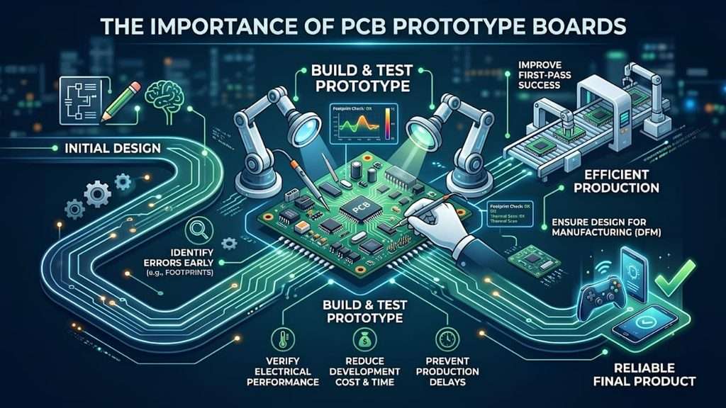
A PCB prototype Board helps engineers verify electrical, mechanical, and assembly performance before manufacturing begins. Instead of discovering expensive problems after fabrication, prototype testing allows teams to identify issues early, improve product reliability, and reduce production costs. IPC also reports that design-related issues account for a significant percentage of electronic product failures.
Why every prototype matters
- Detects footprint and routing errors before fabrication
- Improves first-pass manufacturing success
- Reduces costly PCB redesigns and production delays
- Verifies signal integrity and thermal performance
- Ensures the design is ready for DFM validation
Example
A company developing an IoT controller tested its prototype board and found two incorrect component footprints. Fixing the problem before production took only one day, while discovering it after manufacturing could have delayed delivery by several weeks.
PCB Prototype vs Direct Production
| PCB Prototype Board | Without Prototype Testing |
| Finds design errors early | Errors appear during manufacturing |
| Lower development cost | Higher rework and scrap cost |
| Faster design improvements | Production delays |
| Better product reliability | Increased failure risk |
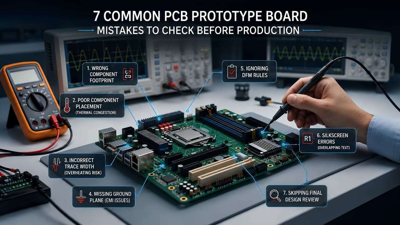
7 Common Prototype PCB Design Mistakes
Even a small mistake on a PCB prototype board can lead to costly rework, production delays, or product failure. Reviewing these common PCB design mistakes before manufacturing helps create a reliable, production-ready board.
1. Incorrect Component Footprints
A footprint that doesn’t match the actual IC or capacitor prevents proper assembly and increases prototype failures.
2. Poor Component Placement
Placing heat-generating components too close together reduces thermal performance and makes PCB assembly more difficult.
3. Wrong Trace Width
Thin traces carrying high current may overheat, reducing the reliability of your PCB layout
4. Missing Ground Plane
An incomplete ground plane increases electrical noise, EMI, and signal instability.
5. Ignoring DFM Rules
Designs that ignore manufacturing tolerances often require redesign before fabrication.
6. Silkscreen Errors
Overlapping reference designators create confusion during PCB assembly and inspection.
7. Skipping Final Design Review
Always run DRC/ERC checks and verify Gerber files before sending your PCB prototype board for manufacturing.
PCB Prototype Board Checklist Before Production
Before manufacturing your prototype PCB, complete this final verification checklist. A few minutes of review can prevent expensive redesigns and improve first-pass production success.
Pre-Production Checklist
- Verify all component footprints match the actual parts.
- Check trace width and clearance for power and signal lines.
- Confirm the ground plane is complete and properly connected.
- Run DRC (Design Rule Check) and ERC (Electrical Rule Check).
- Review Gerber files and drill data before fabrication.
- Validate the BOM to ensure every component is correct and available.
Example
A hardware team designing a smart sensor discovered an incorrect resistor footprint during the DRC review of its prototype PCB. Correcting the issue before fabrication prevented assembly failures and avoided unnecessary manufacturing costs.
Ready to Turn Your Prototype into a Production-Ready PCB?
Avoid costly redesigns and manufacturing delays with expert PCB design, DFM validation, and prototype-to-production support.
Conclusion
A PCB Prototype Board is more than a test board—it is the foundation of a reliable electronic product. By reviewing footprints, trace routing, ground planes, DFM rules, and manufacturing files before production, you can reduce redesigns, improve product quality, and shorten development time.
Whether you’re developing an IoT device, industrial controller, or custom electronic product, a thoroughly validated prototype PCB gives you the confidence to move from prototype to production successfully.
Frequently Asked Questions
1. What is a PCB prototype board?
A PCB prototype board is the first physical version of a printed circuit board used to test functionality, component placement, and manufacturability before mass production.
2. Why is PCB prototype testing important?
Prototype testing helps identify design errors early, reduce manufacturing costs, improve reliability, and avoid expensive redesigns before production.
3. What is the difference between a PCB prototype and a production PCB?
A prototype PCB is built for testing and validation, while a production PCB is manufactured in larger quantities for final product deployment.
4. What are the most common PCB design mistakes?
Common mistakes include incorrect component footprints, poor component placement, wrong trace widths, missing ground planes, silkscreen errors, and ignoring DFM guidelines.
5. What is DFM in PCB design?
DFM (Design for Manufacturing) is the process of designing a PCB so it can be fabricated and assembled efficiently with fewer production issues.
6. How many PCB prototypes should I make before production?
Most hardware projects require 1–3 prototype iterations to validate functionality, fix design issues, and optimize the PCB before mass manufacturing.
7. What files are required for PCB manufacturing?
The essential files include:
- Gerber files
- Drill files
- Bill of Materials (BOM)
- Pick-and-Place file
- Assembly drawings
8. Why is trace width important on a PCB?
Proper trace width ensures that current flows safely without overheating, voltage drop, or reduced PCB reliability.
9. How do I verify a PCB design before fabrication?
Run DRC (Design Rule Check) and ERC (Electrical Rule Check), review Gerber files, validate footprints, and confirm the BOM before sending the design for manufacturing.
10. When should I use a PCB prototype service?
Use a PCB prototype service when developing a new electronic product, IoT device, industrial controller, or custom hardware that requires functional testing before production.